
1. OpenTX Companion software
The OpenTX Companion remote control support software is used for many different tasks, such as loading OpenTX firmware to the remote, backing up model settings, editing model settings, and running the remote simulator.
You can run OpenTX Companion software on multiple computer platforms. OpenTX Companion software supports common systems such as Windows, Mac OS X, and Linux. Even without a remote control, you can experience all the functions and settings of the remote control in a computer simulator.
You can get the latest version of OpenTX Companion software here: http://www.open-tx.org/
1.1. Software Download and Installation
- Download the latest version of OpenTX Companion software from http://www.open-tx.org/.
- Install OpenTX Companion software (take windows version 2.3.6 as an example) Double-click the installer companion-windows-2.3.6.exe.
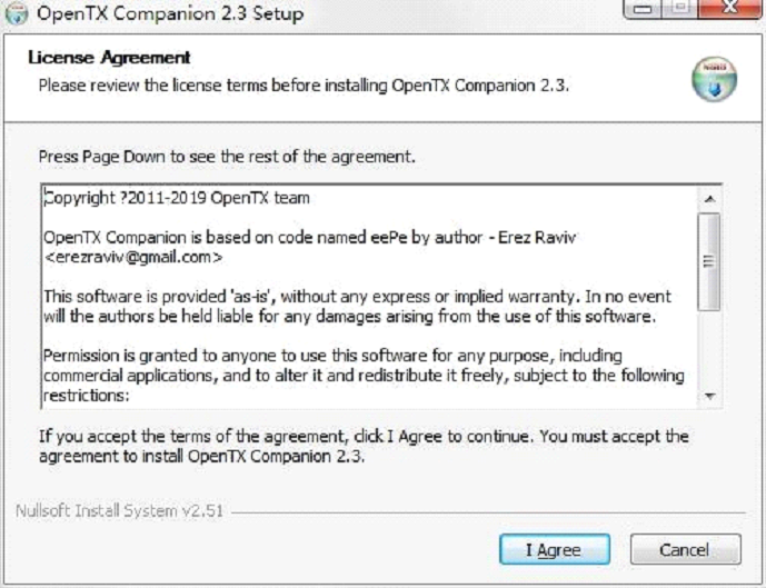
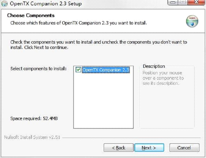
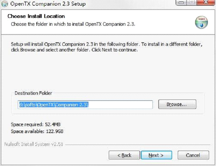
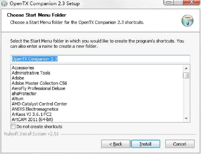
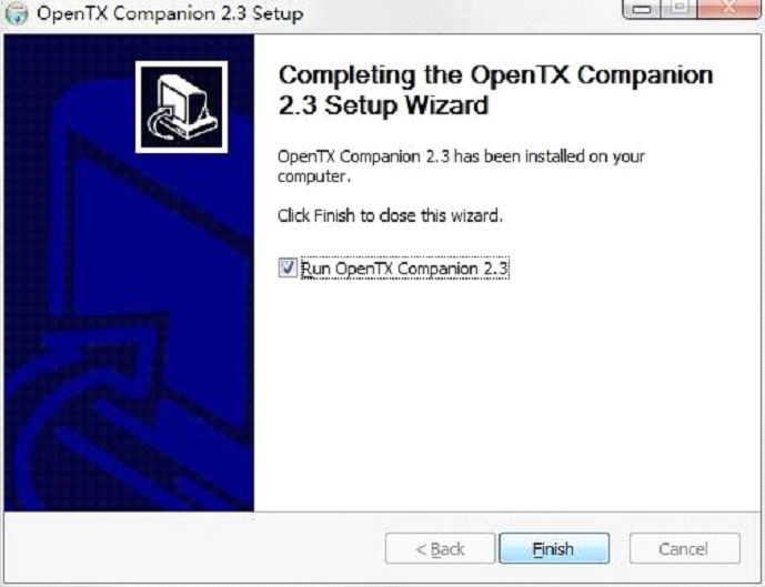
At this point, the OpenTX Companion software installation is complete. Please continue to follow the instructions below to continue setting the software to match the RadioMaster TX16S remote control:
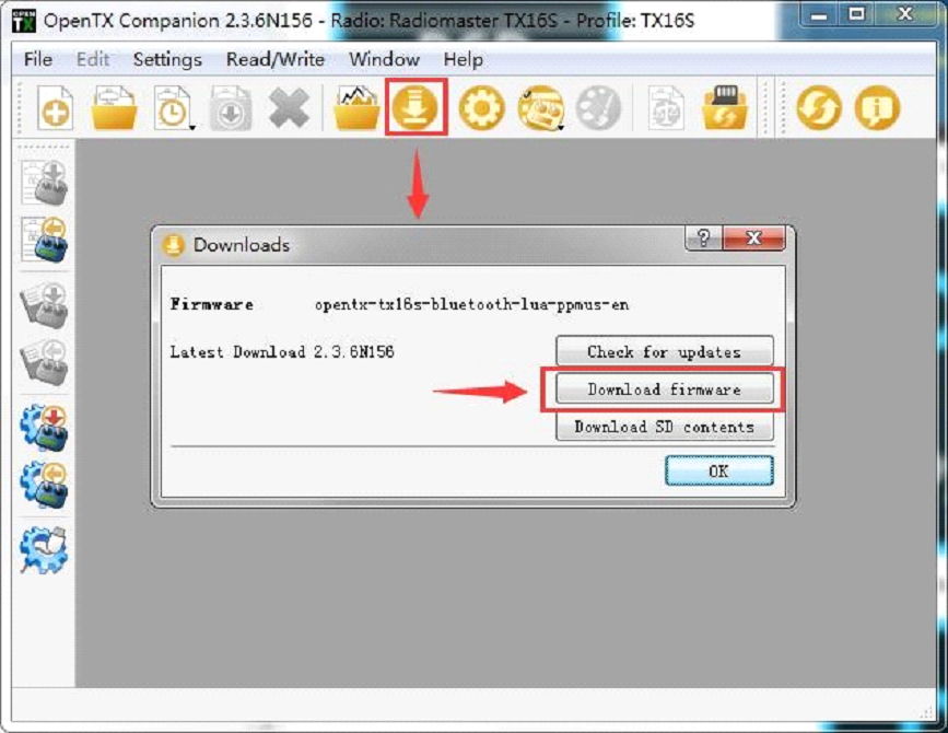
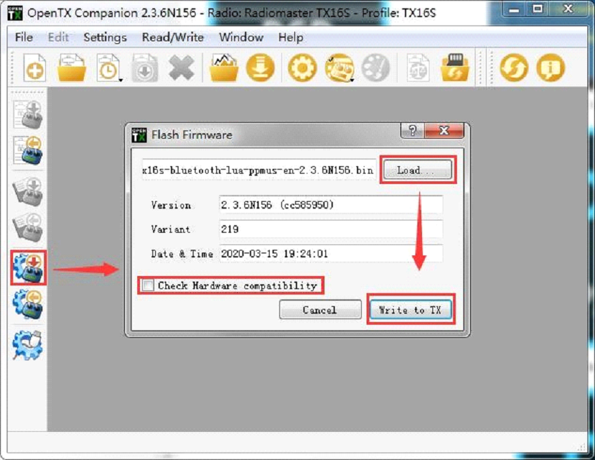
1.2. Use Companion software to upgrade remote controller firmware
After the above settings are completed, click the firmware download button to download the firmware.
Note: The RadioMaster TX16S remote control is pre-installed with stable and reliable OpenTX firmware when it leaves the factory. If there is no special need, please do not update the firmware unneccasarily. Incorrectly flashing firmware may leave your radio inoperable. Only proceed with updates if you are confident in your understanding and ability to do so.
If you are required to update the firmware to for functional upgrades, please carefully follow the instructions below. Before updating the firmware, make sure that all steps are correct and operate carefully to ensure that your remote control is successfully updated.
If not required, please skip this section.
Before writing the firmware, please make sure that the remote control is turned off, and plug in the USB-C (TYPE-C) cable. The following device name will appear in the computer device manager:
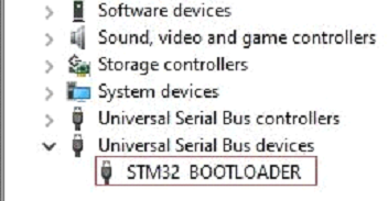
Before writing the firmware for the first time, you need to replace the STM32 BOOTLOADER driver to ensure that the OpenTX Companion software can recognize this hardware type and write the firmware correctly. The replacement method is as follows:
Download the latest version of the universal driver replacement software Zadig.exe from https://zadig.akeo.ie/
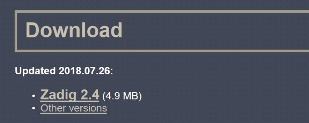
- In the Windows system, right-click Zadig-2.4.exe and select Run as administrator
- In the zadig software, select Options-> List All Devices to view the device list
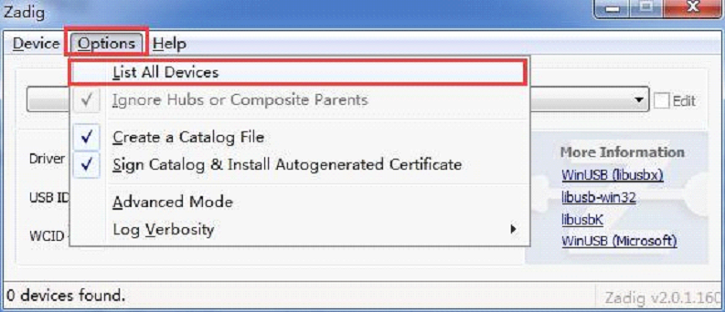
- Drop-down list and find STM32 BOOTLOADER device
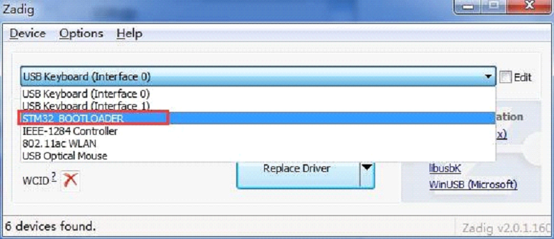
- Click the Replace Driver button (if the driver has been installed before, Reinstall Driver will be displayed) to replace/install the driver. After the driver installation is completed, you can use the OpenTX Companion to write the firmware to the remote controller correctly.
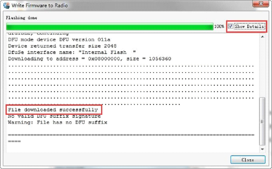
At this point, the firmware of the remote control is successfully written. Unplug the USB-C (TYPE-C) cable and you can use it after booting.
2. First boot
Press and hold the power button to boot. Before entering the main interface, the system will check the position of the throttle stick and switch and other startup conditions. If the startup conditions are not met, there will be a corresponding error prompt. You need to clear it or press any key to jump over.
Throttle warning: This is a warning that the throttle is not at the lowest position when the machine is turned on. You can set the throttle stick to the lowest position or press any key to skip. You can also turn off the throttle state option in the MODEL SETUP menu. Throttle alarm.

Switch warning: This is a warning that the remote-control switch is not in the default position. (The default setting is that all switch directions are up ↑)

Failsafe not set warning: This is a warning that the remote control runaway protection is not set.

Alarm Off Warning: A similar warning will appear if the sound mode of the remote control settings page is set to mute.

SD card warning: The SD card file version used does not match the remote controller firmware version, this warning will appear. The figure requires 2.3V0026 version (the SD card content needs to be updated when upgrading the firmware).

First page: the default first page of the system, you can customize the display elements on the page as required.

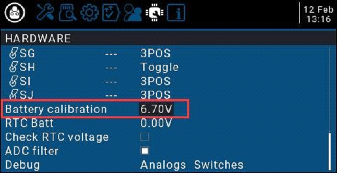
3.1. Calibrate the battery voltage
![]() This example is for using 2 x 3.7v (2s 7.4v) 18650 Li-ion batteries in the supplied tray (batteries sold separately), a 21700 2s 7.4 Li-ion pack (sold separately) or a 2s 7.4v Standard voltage Li-poly pack (sold separately)
This example is for using 2 x 3.7v (2s 7.4v) 18650 Li-ion batteries in the supplied tray (batteries sold separately), a 21700 2s 7.4 Li-ion pack (sold separately) or a 2s 7.4v Standard voltage Li-poly pack (sold separately)
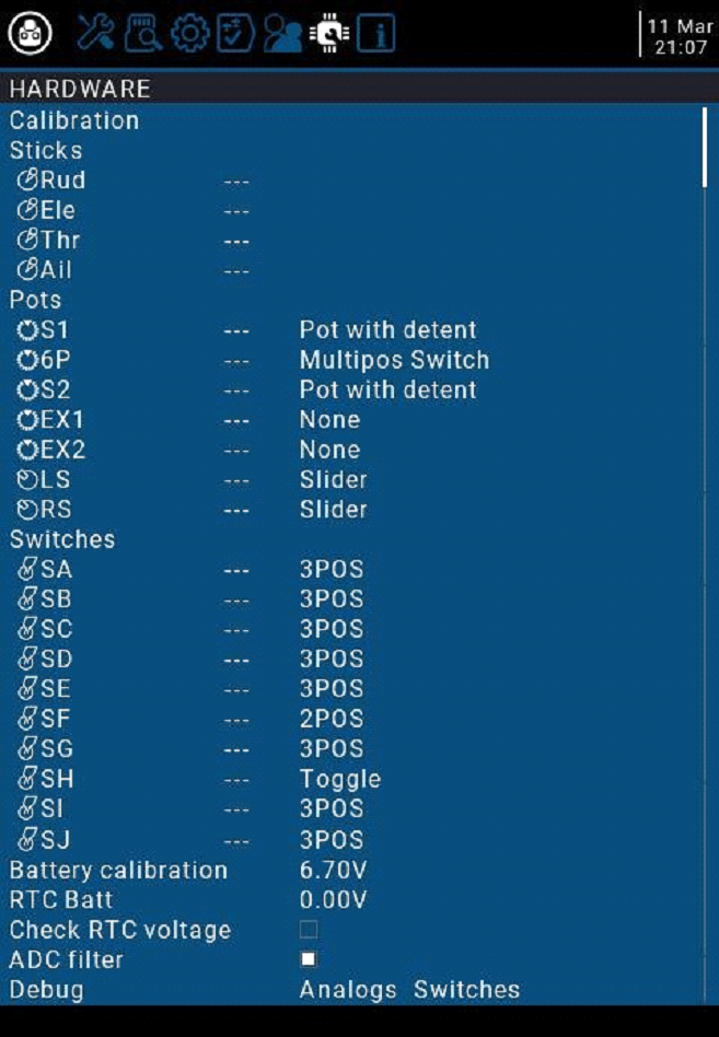
- Press and hold the [SYS] button to enter the system settings. Press the [PAGE] key to the page to the HARDWARE page, scroll to the bottom of the page, select Battery calibration, and fill in the actual measured battery voltage.
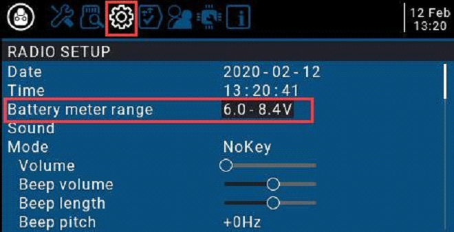
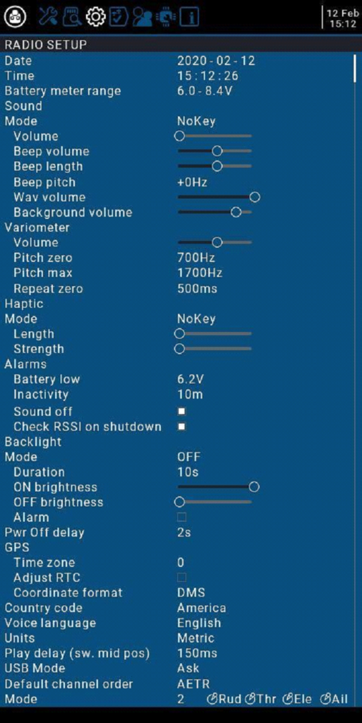
- Scroll to RADIO SETUP, and fill in the battery level range in the Battery meter range as shown below
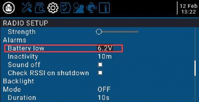
B. On the current page, turn the scroll wheel to find Battery low (low voltage alarm), and fill in the alarm voltage as shown below. When the remote-control voltage is lower than the current set voltage, the system will play a voice and report that the battery voltage is low
3.2. Calibrating Gimbals
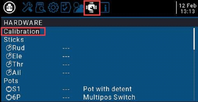
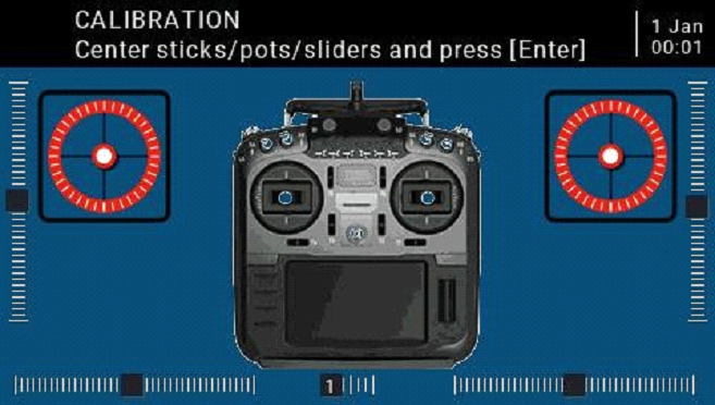
- In the system settings, scroll to the HARDWARE page, select the Calibration item, and press OK to enter the settings.
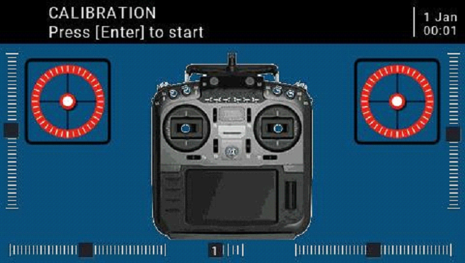
- Follow the text prompts at the top for calibration. The first step prompts, press the confirmation key to start
- In the second step, place all the gimbals, knobs, and side sliders in the middle position. The system obtains the midpoint value, and then press the confirmation key to continue to the next step.
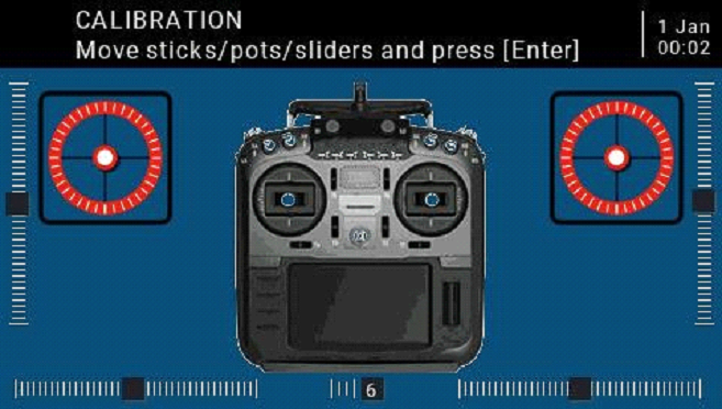
- The third step reminds that all the gimbals, knobs, and side sliders of the paddle move the maximum and minimum. The system saves the maximum and minimum values. At this time, 6POS (six-speed button) may be pressed one by one. The system records the value of each button. The value of the key can be viewed at the bottom of the page. After all the above steps are completed, press the OK key to complete the calibration, and the system automatically returns to the previous page.
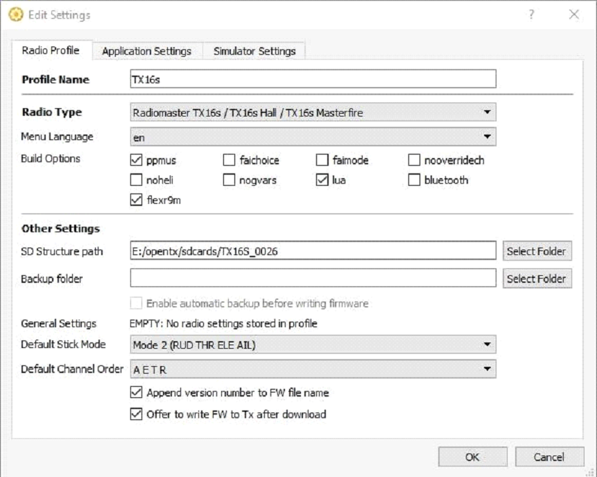
3.3. Set the default Gimbal mode and the default channel output order.
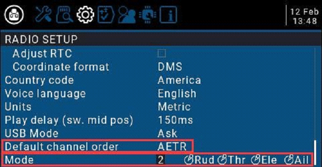
In the system settings, turn the page to the RADIO SETUP page, select the scroll wheel to the bottom of the page, you can see
Default channel order Mode (Gimbal Mode)
Because the channel input order of the built-in multi-protocol transmitting module (high-frequency head) of the RadioMaster TX16S remote control is AETR, in the Default channel order option, be sure to select the AETR order
The last Mode (gimbal mode) can be selected according to your personal preferences:
Mode 1 (right-hand throttle / Japan) or
Mode 2 (left-hand throttle / American)
The icons on the right from left to right indicate the names of the gimbals corresponding to the position of the gimbal on the remote control.
Left gimbal landscape Left gimbal portrait Right gimbal portrait Right gimbal landscape
Rud = (direction) Thr (throttle) Ele (pitch) Ail (roll)
4. Remote control menu details
4.1. Main interface
The default startup screen is as follows. The user can add the content to be displayed to customize the main interface.
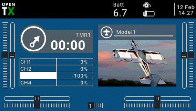
Top menu bar: The default top menu bar displays speaker volume, remote control battery level, receiver signal strength (RSSI), and time and date. Batt is a custom top display remote control voltage; users can also add other display information.
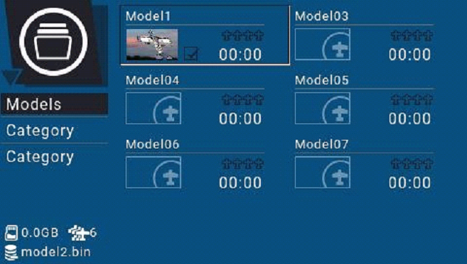
Model menu bar: The model menu bar on the right shows the model name and model picture currently in use.
4.2. System settings
Long press the left SYS button to enter the system setting page. The system setting page is divided into 7 sections.
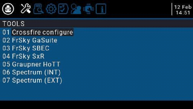
-TOOLS: Tool page, which includes the setting function of the spectrum analyzer and some third-party equipment, such as the setting function of TBS Crossfire, Frsky specific receiver settings, and Graupner’s receiver HoTT protocol settings.
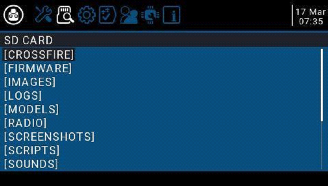
-SD CARD: SD card page. In this page, you can view the contents of the SD card, and quickly set the startup screen, model pictures, and the function of flashing the built-in / external module firmware.
-RADIO SETUP: The remote-control setup page, this page is the basic functions of the remote control and the settings in the default parameters of the remote control.
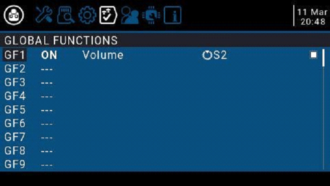
-GLOBA FUNCTIONS: Global function page. This page can customize various global functions. Global functions are similar to special functions in model parameters, but global functions are shared by all model parameters, while functions in model parameters are only used by the current model.
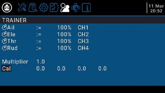
-TRAINER: Trainer aka Coach function page. In this page, you can set the control ratio of each channel from the student mode remote control in the coach mode, and the intervention ratio of the remote control in the coach mode.
-HARDWARE: Hardware setting page. In this page, you can calibrate the gimbal and voltage, set the name of the gimbal, set the functions and names of switches and knobs, and view the underlying parameters of the hardware.
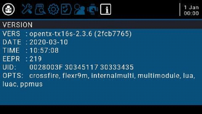
-VERSION: Version page. On this page, you can view the remote controller hardware type, OpenTX firmware version, and the functional items included in the current firmware.
4.2.1 TOOLS (Tool Page) Description
4.2.2 SD CARD (SD Card Page) Instructions
4.2.3 RADIO SETUP Instructions
4.2.4. GLOBAL FUNCTIONS (Global Functions Page) Instructions
4.2.5. TRAINER (coach function page) description
4.2.6. HARDWARE (Hardware setting page) Description
4.2.7. VERSION (Version page) description
4.3. Model selection
4.3.1. Create model and model selection
In the main interface, press and hold the ENT key to pop up the menu (ENT is the wheel button)
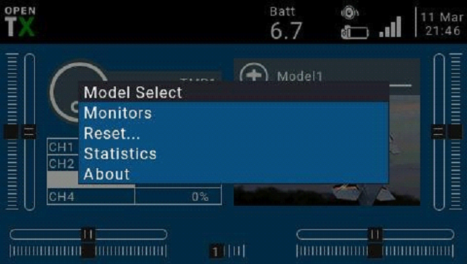
Select Model Select to enter the model selection page, which is used to create, switch, delete, and copy models.
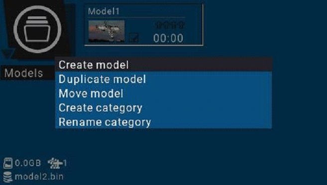
Long press ENT to pop up the model operation menu
4.3.2. Channel monitor
Monitors: used to display the monitoring interface of channel output, mixed control output, and logic switch.
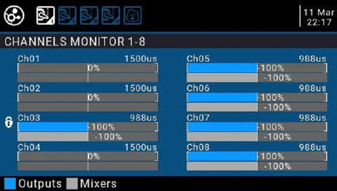
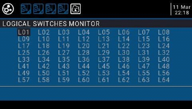
You can use the PAGE key to switch to other interfaces.
The logic switch page can display the status of 64 logic switches. By default, the active state is gray, and black is the active state.
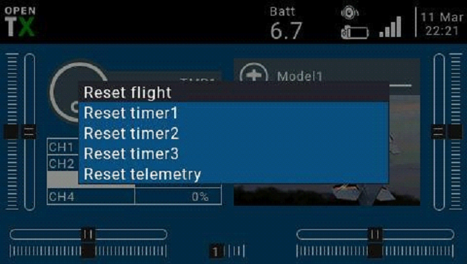
4.3.3. Reset function
4.4. Model Setup
4.4.1 Model settings
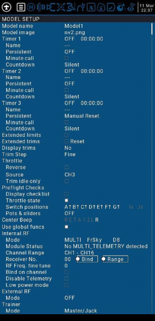
Model Setup detailed options:
Model name:Enter your model name here.
Model image:You can select a picture file as the model logo in the BMP folder of the SD card. Pictures can be viewed using the SD card manager.
Timer1-3:
Up to 3 fully programmable timers that can count up or down.
| ON | Timer is always on |
| Tht | Start timing the first time the throttle stick is pushed up |
| THs | Push the throttle stick to timing, pull the throttle stick to the end to stop timing |
| TH% | Dynamically changing timer speed based on throttle stick percentage |
| Time Value | When set to 0:00, it will count down from 0, otherwise it will count down from the preset value. |
Name:Name the timer
Persistent: The timer keeps shutting down. Checking it means that the timer value is stored in the memory when the remote control is powered off or another model is replaced, and it will be reloaded next time the model is used.
Minute call:Check this option to announce the current timer time every minute
Countdown:Countdown broadcast, default 10s (10 seconds)
| Silent | Quiet mode |
| Beeps | Beep |
| Voice | Voice broadcast countdown |
| Haptic | Vibration alert |
Extended limits:Expand the limit. After checking, set the channel rudder limit to
± 125% (default maximum ± 100%).
Extended trims : Fine-tuning extension, allowing fine-tuning to cover the entire gimbal range, instead of ± 25%
Display trims:Modify the precision of the fine-tuning step. The accuracy can be modified according to actual requirements.
Throttle:Throttle related settings
Reverse:Throttle reverse
Source : Throttle operation source (input source), because the throttle trigger timer is used, such as the THs function, it is usually set to the throttle channel instead of the gimbal, so that the throttle lever operation triggers the timer correctly
Trim idle only : Throttle trim only affects the low position, where trim only affects the idle part of the throttle stroke and does not touch the entire throttle range.
Preflight Checks : Pre-flight check, when booting or loading the model, the system will check the following default settings, if it does not match the following model settings, the system will pop up a security warning page
Display checklist:Show checklist
Throttle state:Throttle status warning, when the remote control is powered on or the model is loaded, if the throttle stick is not at the lowest position, a warning will be issued
Switch positions : Switch position check, defines whether the remote control checks whether the switch is in a predetermined position when the remote control is powered on or when loading a model. To set them, place all the switches in the way you like, and then press and hold ENT (the confirmation key), the system will save all current switch positions as default values
Pots & sliders:Check the position of the knob and slider. The default position of the preset knob and slider is the same as above.
Center Beep:Center prompt sound, select whether the gimbal, knob and slider will emit a prompt sound when reaching the center point.
Use global funcs : Use global function settings, choose whether to apply global function settings to the current model
Internal RF:Built-in wireless RF module, built-in 4in1 multi-protocol RF module, please refer to multi-protocol RF module manual for usage
External RF:External RF module, compatible with many mainstream RF modules
Trainer:Trainer Mode
Mode:
| Master/Jack | Audio cable connection, coach host mode |
| Slave/Jack | Audio cable connection, student slave mode |
| Master/Bluetooth | Bluetooth wireless connection, coach mode (requires external Bluetooth module) |
| Slave/Bluetooth | Bluetooth wireless connection, student slave mode (requires external Bluetooth module) |
| Master/Multi | 4in1 multi-protocol module coach host mode (This function needs to add an external 4in1 multi-protocol module as coach input receiver RX mode) |
4.4.2. Flight Mode(Flight Modes)
The flight mode allows you to set the corresponding fine-tuning value for a specific mission or flight behavior. This item is mainly used for fixed-wing gliders to use different fine-tuning values in different environments. You can customize the fine-tuning value of 1-6 channels, and you can set it for each flight. Mode setting smooth slow-in slow-down time.
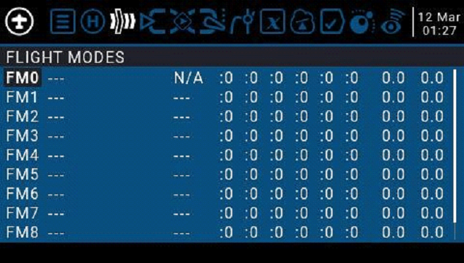
There are 8 flight modes plus the default FM0 available. The first item of FM1- FM8 requires a trigger switch. When no switch is on, FM0 is enabled by default.
| Name | Define a name for the flight mode |
| Switch | Select the trigger switch for the flight mode. It can be a physical switch or a logical switch. |
| Trim selection array | Adjust the fine-tuning value of 1-6 channels according to your actual needs |
| Fade in Fade Out | Slow Ease In / Ease Out Time Settings |
| Check Flight Mode Trims | At the bottom of the screen (below FM8) you are reminded to check the fine-tuning of each flight mode. According to the currently selected FM number, the corresponding reminder message is displayed, for example, if the flight mode FM2 is active, it will display “Check FM2 trims” |
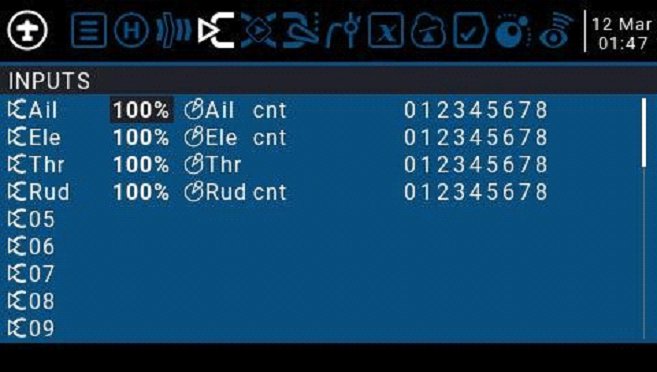
4.4.3. Input Source
The Inputs page defines the input source. Before outputting to the channel, you can make preliminary settings for the input source, such as limiting the amount of operation, increasing the curve, using the switch pair to switch, etc.
The input source can be a physical operation source such as a gimbal, knob, or switch of the remote control, or it can be a global variable Gvar, a logical switch, return data, etc.
To set an entry, press and hold the ENT key on the current entry and a submenu will pop up
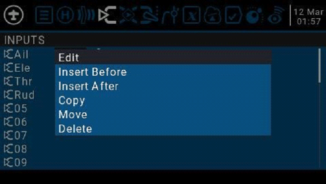
Edit
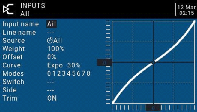
Input name: Name of the current entry. Use the scroll wheel to select a letter or number. Press and hold the ENT key to switch between upper and lower case. Press the ENT key to switch to the next character.
Line name: Because each entry can have multiple lines of configuration, you can give each line a name to avoid confusion in the future
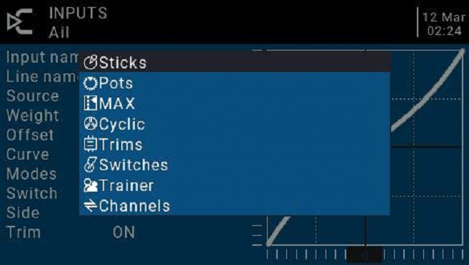
Source: Press and hold the ENT key to enter the input source selection menu. Scroll up or down to the desired category and press ENT to select the corresponding input source
Weight: Normal range is a value between ± 100% will be zoomed to the gimbal operation. If you enter a negative value, for example -100% means reverse the output. Note that channel inversion should not use negative values on the Inputs page, and to reverse channels should be reversed on the Outputs page.
Offset: Midpoint offset setting
Curve: Curve settings
| Diff | Adjust the stroke amount on one side with the midpoint as the boundary | |
| Expo | Expo curve setting. Increasing a positive value will make the gimbal smoother and smoother when approaching the midpoint, while increasing a negative value will make the gimbal more acute when approaching the midpoint. | |
| Func Preset function | X>0 | Positions above 0 (midpoint) follow the gimbal output, operations below the midpoint are all fixed to the midpoint value of 0 |
| X<0 | The opposite of the previous one | |
| |X| | Absolute values, negative values less than the midpoint will always become positive values, and the actual performance is a V-shaped curve | |
| f>0 | Below the midpoint 0 is fixed at midpoint 0, above the midpoint is fixed at 100, the actual performance is that the gimbal becomes 0 and 100 to switch, there is no intermediate process | |
| f<0 | The opposite of the previous one | |
| |f| | Above the midpoint is fixed at + 100%, and below the midpoint is fixed at -100%. The actual performance is that the gimbal becomes -100% and + 100% to switch. There is no intermediate process. | |
| Cstm | Call custom curve (CV1-CV32), custom curve is set in curve page CURVE |
Modes: Select the corresponding flight mode, and the output trimming value that affects this entry can be set by the flight mode entry
Switch: Select the switch to activate this item (Note: This setting is added to this item to add multiple lines of different settings to switch, if there is only one line setting, do not set the activation switch, otherwise the switch will cause this item to be completely invalid)
Side: Unilateral setting with the midpoint as the boundary. No matter how this item is set, it will be set to unilateral effect by Side.
| x>0 | All below the midpoint are fixed at 0, and normal output above the midpoint |
| x<0 | All above the midpoint is fixed at 0, and normal output below the midpoint |
Trim: You can choose whether the fine-tuning is effective for this entry, or you can define a fine-tuning that affects this article separately.
4.4.4. Mix control (Mixer)
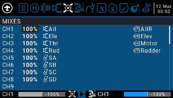
Mixing page for channel settings
The mix control page allows you to combine as many input sources as you want and map them to any one or more of the 32 output channels. Finally use the next page (Outputs) to make these purely logical outputs to fit the model device
You have complete flexibility in controlling the mixing from any input to any output channel.
A mix puts one input into one channel. The inputs are configured in the Inputs page, which defines any input type.
The mixing control page can also use other channels as the source of the current channel, and output from the current channel after re-mixing. It can also mix one or more channels to another or multiple channel outputs, which can combine very powerful complex functions.
All inputs range from -100% to + 100%. Gimbals, knobs, sliders, channels, global variables, and coach input.
If you want the servo of the No. 2 plug connected to the receiver to be controlled by lifting (ELE), you only need to create a mixing entry on CH2 and use the Ele input as the source of operation.
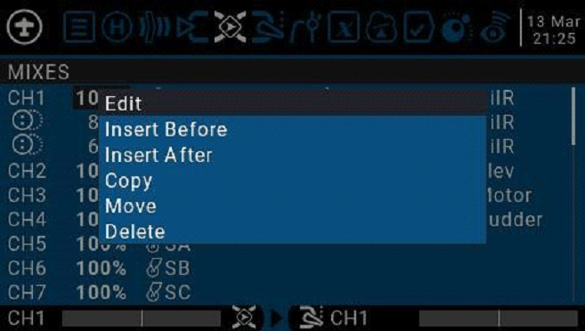
Each channel can have many lines, and you can choose the operation between each line. Long press the ENT key and select Insert Before / After to create a new line.
By default, all lines on the same channel are added together, and the next line can choose to be superimposed or multiplied with the channel value of the previous line, and replaced completely.
Please note that the currently active row of settings will be displayed in a bold font, making it easy to recognize the item currently in use at a glance. The CH1 channel shown in the figure is input by the Ail gimbal, and the three states of the SA switch are used to switch three-stroke amounts.
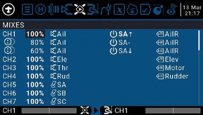
To edit a mixing control, use the scroll wheel to select the mixing control item up and down, and press and hold the ENT key to enter the editing submenu. Select Edit and press the ENT key momentarily.
Detailed settings for mixing entries
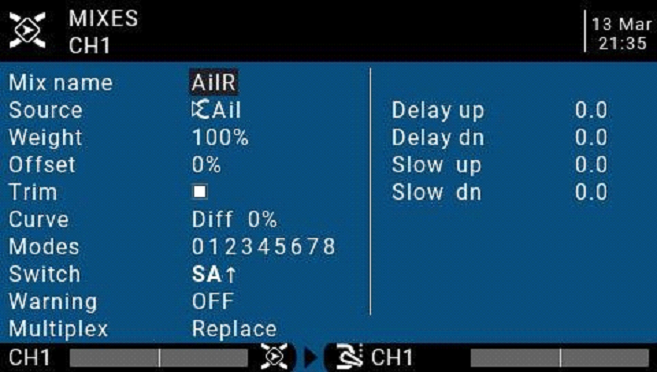
Mix name: Name setting Use the scroll wheel to select letters and numbers, and press and hold the ENT key to switch between upper and lower case. Short press the ENT key to set the next character.
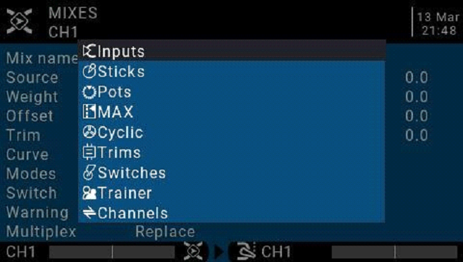
Source: Long press the ENT key to pop up the input source category menu.
Weight: Channel travel amount, the range is -500 / + 500. The default value is 100. Negative values indicate reverse channel output.
Offset: Midpoint offset, you can add the offset of the input value, positive or negative. Range is -500 / + 500
Trim: You can choose whether the fine-tuning is effective for this entry, or you can define a fine-tuning that affects this article separately.
Curve: Curve settings
| Diff | Adjust the stroke amount on one side with the midpoint as the boundary | |
| Expo | Expo curve setting. Increasing a positive value will make the gimbal smoother and smoother when approaching the midpoint, while increasing a negative value will make the gimbal more acute when approaching the midpoint. | |
| Func Preset function | X>0 | Positions above 0 (midpoint) follow the gimbal output, operations below the midpoint are all fixed to the midpoint value of 0 |
| X<0 | The opposite of the previous one | |
| |X| | Absolute values, negative values less than the midpoint will always become positive values, and the actual performance is a V-shaped curve | |
| f>0 | Below the midpoint 0 is fixed at midpoint 0, above the midpoint is fixed at 100, the actual performance is that the gimbal becomes 0 and 100 to switch, there is no intermediate process | |
| f<0 | The opposite of the previous one | |
| |f| | Above the midpoint is fixed at + 100%, and below the midpoint is fixed at -100%. The actual performance is that the gimbal becomes -100% and + 100% to switch. There is no intermediate process. | |
| Cstm | Call custom curve (CV1-CV32), custom curve is set in curve page CURVE |
Modes: Select the corresponding flight mode, and the output trimming value that affects this entry can be set by the flight mode entry
Switch: Select the switch to activate this item (Note: This setting is added to this item to add multiple lines of different settings to switch, if there is only one line setting, do not set the activation switch, otherwise the switch will cause this item to be completely invalid).
Warning: Set the alert tone
Multpx: Superposition method, output after superimposing with the value of the previous stroke amount
Add: Additive superposition, the current value is added to the value of the previous line and output
Multiply: multiplication, the current value is multiplied by the value of the previous line and output
Replace: direct replacement, the value of the previous line is directly replaced by the value of this line
The combination of these operations allows the creation of complex mathematical operations and is often considered one of the biggest benefits of using OpenTX.
Delay Up/Dn: The response of the output can be delayed as the input changes. (In seconds).
Slow Up/Dn: Regarding input changes, the response of the output can be slowed. For example, slow speed can be used to slow down retraction driven by a normal proportional servo. The output will cover the time in seconds from 100 to + 100%.
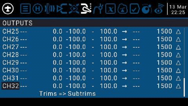
4.4.5. Outputs
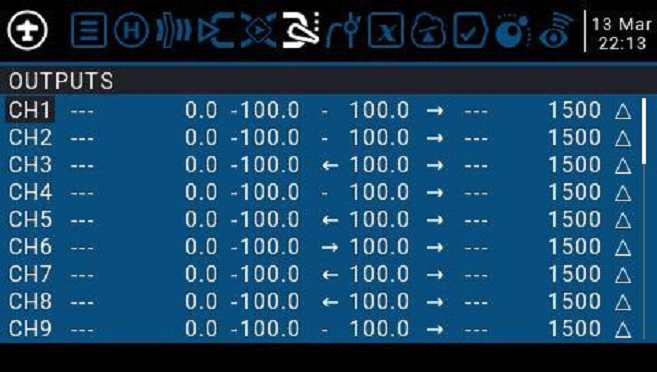
Total output page, final channel output overall settings
4.4.6 Curves
The curve can be used to modify the control response in the Inputs, Mixes, or Outputs page. Standard curves containing Expo and Differential can be used directly in these sections. This page is used to customize any kind of curve.
Can set up to 32 curves
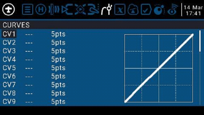
The curve can be between 2 and 17 points and can have a fixed or user-definable x coordinate.
X value represents input, such as the course of the gimbal from low to high
Y value represents output, such as the process of channel output from low to high
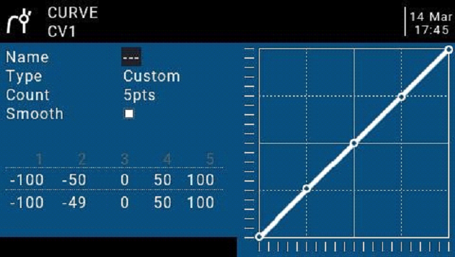
Name:Name the curve, easy to find when recalling the curve in other settings
Type:Curve type
| Standard | Standard type, only Y point (output) can be edited, ranging from -100 to 100 |
| Custom | Custom types, both X (input) and Y (output) points are editable, ranging from -100 to 100 |
Count: The number of points on the curve, between 2 and 17.
Smooth: If checked, create a smooth curve through all points.
When customizing, move the cursor to X and Y coordinates, and change the position of each coordinate point according to your needs.
Depending on the type selected above, this allows writing the X coordinate of a standard curve, or the X and Y coordinates of a custom curve.
Long press the ENT key on the coordinate point to enter the submenu:
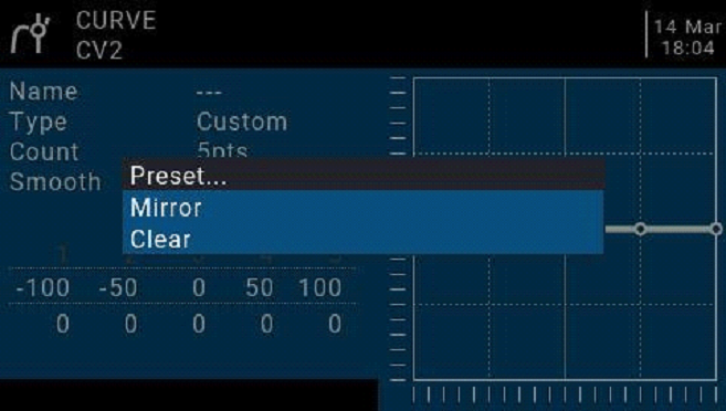
Preset: Select presets with slopes of -45 °, -33 °, -22 °, -11 °, 0 °, 11 °, 22 °, 33 °, 45 °. When defining more complex curves, choose reasonable presets will reduce some steps.
Mirror:Mirror the curve vertically.
Clear:Clear the current curve.
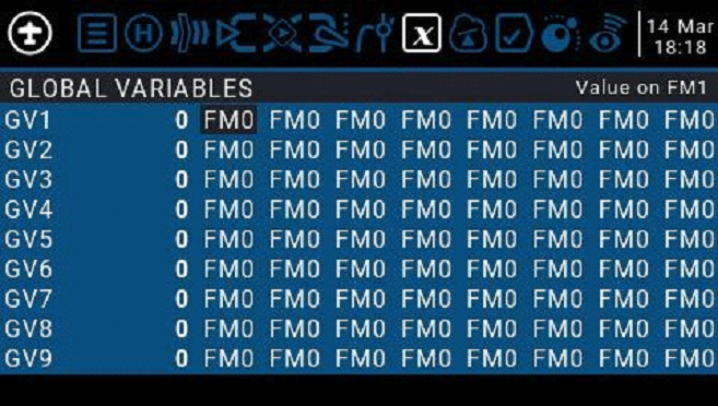
4.4.7. Global variables
Global variables are customizable values that can be used as temporary values for custom operations. In complex functions, the values of global variables are automatically modified through certain trigger conditions for conditional judgment or any other purpose. Global Variables can be used as input or output real-time adjustment parameters, and can also be used as parameters in flight mode and curve definition. Global variables can be used in any place where numerical values can be entered to achieve some automated control.
They are also specific flight modes, which avoids having to use separate mixing lines with different values for each flight mode. This greatly simplifies mixing pages and makes them easier to understand.
By using the “Adjust GVx” option in the Special Functions page, you can even adjust global variables on the fly, so you can quickly optimize settings such as double- rate ratio, exposure, differential, flap to elevator conversion, and more. If pop-ups are enabled (indicated by! Next to the GV label), when the variable is updated, a pop-up window with the variable name and new value will be displayed on the main view.
“Global” means that global variables can be used to set pages for the entire model, but not for all models. Each model has its own set of global variables.
There are 9 global variables available.
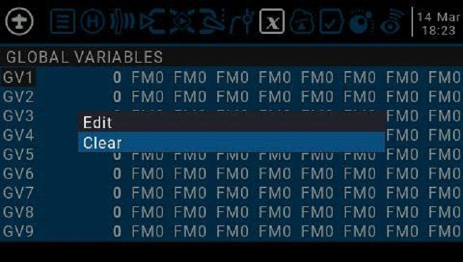
Modify the value directly or press and hold the ENT key to pop up the sub-menu to change the type and parameter of the global variable.
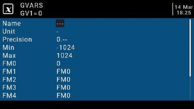
Name: Setting name
Unit: Units, switchable between normal and%
Precision: Precision, which can be used in decimal mode. You can set this mode corresponding to the percentage.
Min: Minimum value, which can be limited when the value is changed dynamically
Max: Maximum value, which can be limited when using dynamic change values
FM0-FM8: You can specify a value for each flight mode or set it to be the same as the other flight modes. Press and hold the ENT key to switch the input value and select the flight mode in this field. When editing a value, it will increment / decrement by 1 or 0.1, depending on the “Precision” setting above.
4.4.8. Logic switches
The logic switch is a user-programmed virtual switch. Like the physical switch, the logic switch is also a switch, but unlike the visible switch, which can be moved by hand, the logic switch is an internal switch triggered by some conditions. The judgment condition you set allows the remote control to automatically turn on or off the logic switch to achieve a certain or a series of automated actions.
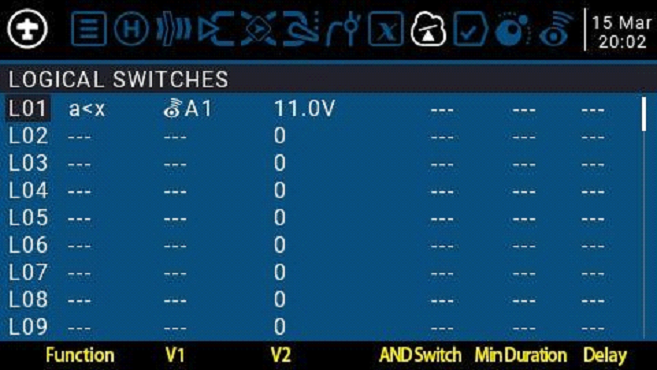
The setting of the L01 example in the figure is expressed as follows: When the return value A1 is less than 11.0V, the L01 switch is automatically turned on. In the settings of other pages, L01 has the same function as the physical switch. You can define the corresponding function for L01 on or off. In this way, a switch is automatically executed according to the parameters that change in real time.
The remote control system provides 64 logic switches, each of which has three judgment methods:
- Compare the values of parameters a and b, a corresponds to V1, b corresponds to V2, a and b can be any source, such as input source, channel, switch, or return item, etc.
- Compare the value of parameter a and data x, a corresponds to v1, x corresponds to v2, and x is a fixed value, which is used to compare with parameter a
- Parameter a can be compared with its own calculation result. For example, the change of parameter a itself can affect the current state of the logic switch.
Functions
| a=x | Triggered when the parameter v1 is equal to the data v2. For example, if the thr gimbal is less than -90, the current logic switch is turned on when the thr gimbal is less than -90%. |
| a~x | Triggered when the parameter v1 is approximately equal to the data v2, approximately equal to the range of about 10% |
| a>x | Triggered when parameter v1 is greater than data v2 |
| a<x | Triggered when parameter v1 is less than data v2 |
| |a|>x | Triggered when the absolute value of parameter v1 is greater than v2, the absolute value is that it will become positive no matter whether it is positive or negative |
| |a|<x | Triggered when the absolute value of parameter v1 is less than v2 |
| AND | AND operation is triggered when both parameters v1 and v2 meet the conditions. For example, v1 is the switch SA ↑ and v2 is SB ↑ , which indicates that the current logic switch can be turned on when both SA and SB switches are in the ↑ position. |
| OR | OR operation, which can be triggered when one of the parameters v1 and v2 meets the conditions, or when all the conditions are met |
| XOR | Exclusive OR operation, triggered when one of the parameters v1 and v2 meets the conditions, not triggered when all the conditions are met or all the conditions are not met |
| Edge | Is a momentary switch (very short duration, about 30 ms), it will be triggered when V1 meets the conditions V1: Can be physical switch, logic switch, trim button V2: It is divided into two parts [t1: t2], t1 is the minimum value, and t2 is the maximum duration of V1. The logic switch is triggered only after t1 when V1 meets the conditions, and is closed before t2. If t2 is left as “—” then only t1 is applicable. When V1 changes from on to off (ie falling edge), the logic switch will be triggered, and then the logic switch will be turned on for 1 processing cycle (about 30 ms). If t2 is set to “<<“, the logic switch (ie, rising edge) is triggered when V1 changes from off to on. |
| a=b | Triggered when the parameter v1 is equal to the parameter v2. For example, when the value of the thr gimbal and the value of the ail gimbal are equal, the type of v2 at this time is not digital data, but a source |
| a>b | Triggered when parameter v1 is greater than parameter v2 |
| a<b | Triggered when parameter v1 is less than parameter v2 |
| △≥x | △ is the mathematical symbol Delta (difference value). It is triggered when the difference of the parameter v1 itself is greater than or equal |
| to the value of data v2. Switch, this item only judges the difference when v1 changes from small to large | |
| |△|≥x | Triggered when the absolute value of the difference of the parameter v1 itself is greater than or equal to the value of v2. This judges the absolute value. Since the negative value also becomes positive, a change from v1 to v or from v1 to trigger the current logic switch |
| Timer | The switch that automatically loops all the time. V1 is the on time and v2 is the off time. It can be defined by v1 and v2 to automatically cycle at constant intervals. |
| Sticky | v1 can only switch on, v2 can only switch off |
AND Switch: With the arithmetic switch, this item can set any physical switch and logic switch. The current logic switch can be triggered when the switch set by this item and the current item meet the conditions
Duration: Hold time, the length of the current logic switch after it is triggered. If there is no parameter, the default is always on. If this item is set for time (0.1-25 seconds), the current logic switch will automatically turn off after this time.
Delay: Delay, after the trigger is turned on, the range is 0.0 to 25 seconds.
4.4.9. Special Functions
The combination of logic switches, special functions, global variables, and passback items opens up a variety of exciting new features for the RadioMaster TX16S. E.g:
-Changes in battery voltage data returned by the receiver can trigger voice alerts
-Altitude data returned from the barometer on the aircraft, real-time broadcast of the aircraft’s altitude
-By defining voice for the switch, real-time voice broadcast operation on the remote control
-Use logic switches and global variables to let the remote control perform a single or a series of automated actions
-Call lua scripts with switches or logic switches for more advanced custom functions
-Use the knob to adjust the volume
-Use the switch to adjust the backlight brightness
In addition to a few of the commonly used methods listed above, the ever-changing features allow you to realize your imagination
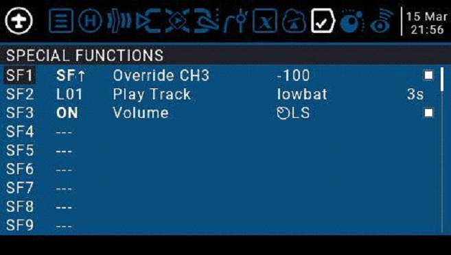
The three examples in the picture are represented as:
SF1:When the SF switch position is ↑, the CH3 channel will be covered by -100. Usually this setting is used to lock the throttle.
SF2:When the logic switch L01 is automatically turned on, lowbat (low battery voltage) voice will be broadcasted. The rightmost 3s means that the voice will be broadcasted every 3 seconds. Automatically turn on when
SF3:When the remote control is activated, the LS slider is defined as a function to control the system volume
Each model can have 64 special functions. In addition, there are 64 global settings that are common to all models. To use the global function, please enter the Global Functions page in the remote control system settings to set it.
Each setting is activated with a trigger switch. You can select physical switches, logical switches, fine-tuning buttons, and flight mode. There are two other special options, ON and Ones (which are always enabled when the machine is turned on), and One (which is performed only once when the machine is turned on)
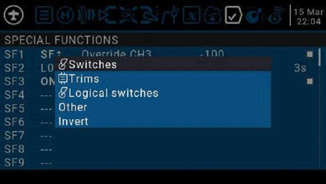
Press and hold the ENT key to enter the sub-menu for displaying sources by category. Scroll up or down to select the desired category and press the ENT key.
The following functions are triggered by the switch selected above
| Override | Override channel value |
| Trainer | Coach mode enable switch, it is recommended to set to SH rebound switch, this switch is used to activate or stop the operation of the student machine |
| Inst.Trim | One-touch saves the current gimbal position as a fine-tuning value |
| Reset | Reset, you can choose to reset all or reset one way individually. The content of the reset option is the same as that in the main interface. |
| Set Time | Used to set the timer, set the timer time and turn on when the switch is turned on |
| Adjust | Adjust the global variable Gvar and enter a fixed number directly Press and hold the ent pop-up menu to change the way to set Gvar. There are three options: Mixer Source: Set the value of Gvar with an input source Global var, another global variable Inc / Decrement: increase or decrease |
| Volume | Select a knob or slider to adjust the volume |
| SetFailsfe | Use the switch to set the receiver’s runaway protection anytime, anywhere |
| Play Sound | Play a sound ! 1x: Play sound once, not at startup |
| 1x: Play sound once. 1s-60s: broadcast at intervals (seconds) | |
| Play Track | Play wav file in SD card, single broadcast and loop broadcast are the same as above |
| Play Value | Voice broadcast value, can broadcast values from any source, such as real-time values such as gimbal, voltage, altitude, time, etc. |
| Lua Script: | Call the specified script, and the script file should be placed in the / SCRIPTS / FUNCTIONS / folder of the SD card. |
| BgMusic | Background music, loop play wav files, take effect immediately after power on |
| BgMusic II | Pause background music |
| Vario | Broadcast Vario value |
| Haptic | shock |
| SD Logs | Start recording logs, save on SD card, can set time interval 0.2-25.5 seconds |
| Backlight | To control the brightness of the backlight, you must first define the backlight ON and OFF brightness in the system settings. This uses the switch to switch the corresponding ON and OFF brightness of the backlight. |
4.4.10. Custom Scripts
Custom script allows you to customize the functions of the remote control. The scripting language used is Lua, which is a lightweight embeddable scripting language. You need to implement custom functions in the remote control. There are three basic types:
One-time: The script runs only once and then terminates. Initialization of some parameters, and a wizard for creating a new model. The script is stored in the SCRIPTS folder of the SD card.
Mix: A script that executes in a loop, similar to the main program, and is always executed during remote operation.
Function: The script is called in Special Functions. This script is only allowed to execute when the switch in the special function is turned on, and closed when the switch is turned off.
There are some caveats-if the script stops executing, you should never use Lua model scripts to control any aspect of the model that might cause a crash. The reason is that if the script tries to use too much CPU time or memory, it will be closed and it will not run again when the model is selected.
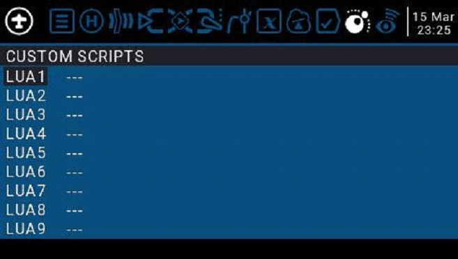
The Custom Scripts page is for mixed-type scripts that run continuously. These scripts should be placed in the / SCRIPTS / MIXE/folder of the SD card.
There can be up to 9 custom scripts.
For script development and documentation, please refer to the OpenTX 2.3 Lua Reference Guide:
https://legacy.gitbook.com/book/opentx/opentx-2-3-lua-reference-guide/details
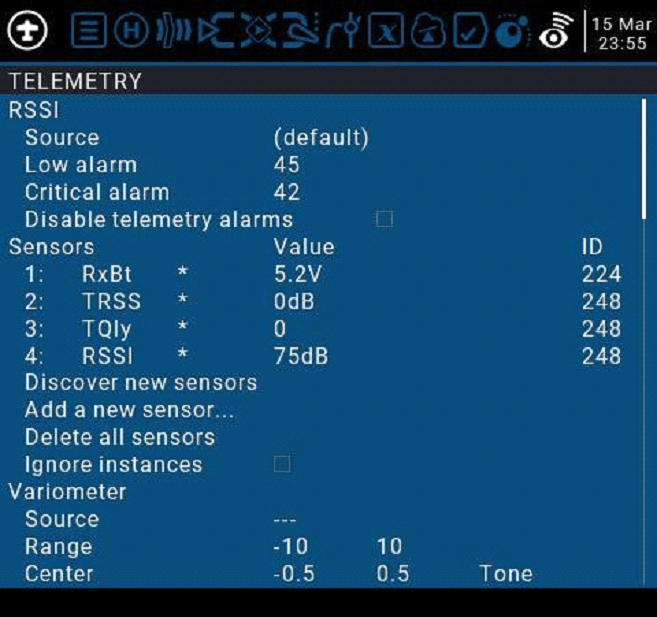
4.4.11. Digital Transmission and Telemetry
Each value received via digital transmission is considered a separate sensor with its own properties. Multiple identical sensor types can be connected, but the physical ID must be changed. For example, a sensor for each battery in a 2-6S lithium battery, or monitoring individual motor currents in a multi-motor model. Each sensor can be reset individually with special functions.
Receiver Signal Strength Indicator (RSSI): The value transmitted by the receiver in the model to the remote control, indicating the strength of the received signal. The warning can be set to warn when it is below the minimum, indicating that you are in danger beyond the flight range. Factors affecting signal quality include external interference, long distances, poor steering or antenna damage, etc.
It is not an absolute measurement, but a number that represents the ratio of the signal to some initial “good” value. The number is relative, but can indicate that the model may be close to the range limit of the controlling aircraft.
When the return signal is completely lost, the remote control will prompt “Lost return signal”. Please note that due to a failure of the return link, the remote control can no longer warn you of RSSI or any other alarm conditions, so no further alarm sounds.
Digital settings:
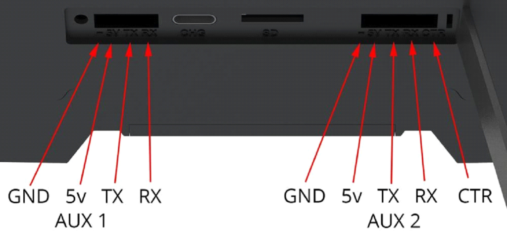
5. External UART
The TX16s has two externally accessible 5v UART ports that are direct output non- inverted TTL. Aux 1 is a 4 pin TTL UART, Aux 2 is a 5 pin TTL UART with a CTR connection directly to the Radios MCU.
![]() IMPORTANT NOTE!
IMPORTANT NOTE!
Ensure the correct polarity and voltage are applied when connecting to UART interface. Do not apply more than 5v to the UART port at any time.
External UARTS can be used for additional hardware and projects such as:
- Adding a Bluetooth module.
- Updating compatible receivers
- External Telemetry Data
- Antenna Tracking
- And more!
EU Simple Declaration of Conformity
RadioMaster declares the radio equipment TX16s is in compliance with EU directives Directive 2014/53/EU. Full text of the declaration of conformity is available at the following website www.radiomasterrc.com
Manufacturer by
ShenZhen RadioMaster Co., Ltd
5th Floor, Yutian Building, No. 18 Yangtian Road, Xin’an Street, Baoan District, Shenzhen, Guangdong.
FCC ID: 2AV3G-TX16S
FCC Information
This equipment has been tested and found to comply with the limits for Part 15 of the FCC rules. This device complies with part 15 of the FCC rules. Operation is subject to the following two conditions: (1) This device may not cause harmful interference, and (2) this device must accept any interference received, including interference that may cause undesired operation. Full text of the declaration of conformity is available at the following website www.radiomasterrc.com
![]() CAUTION:
CAUTION:
Changes or modifications not expressly approved by the party responsible for compliance could void the user’s authority to operate the equipment. This product contains a radio transmitter with wireless technology which has been tested and found to be compliant with the applicable regulations governing a radio transmitter in the 2.400GHz to 2.4835GHz frequency range.
Antenna Separation Distance
When operating your RadioMaster transmitter, please be sure to maintain a separation distance of at least 20 cm between your body (excluding fingers, hands, wrists, ankles and feet) and the antenna to meet RF exposure safety requirements as determined by FCC regulations.